Bringing Life to the MeArm Robot Arm
Follow article
 Dave from DesignSpark
How do you feel about this article? Help us to provide better content for you.
Dave from DesignSpark
Thank you! Your feedback has been received.
Dave from DesignSpark
There was a problem submitting your feedback, please try again later.
Dave from DesignSpark
What do you think of this article?
Just spotted the new MeArm robot deluxe kit (134-0413) from Mime Industries and fancied doing an out of the box build. I was keen to see it go together and understand how the little arm would perform. Being open source it is ideal for use in your own projects. The Maker Kit is also available in a format where you can use your own controller, be it an Arduino, Raspberry Pi, Beaglebone or others, to control it. You could also customise the actual design of the arm itself by making some of the individual parts cutting out from flat sheet materials.
EDITOR'S NOTE.....
Find MeArm project code for multiple boards at Codebreaker. Select a Project and then select a Board to obtain the code you need.
The kit comes with all of the products needed to construct a complete robot arm together with a Me Brain controller board. The only extra items I needed were a small cross point screwdriver for tightening the servo horn retaining screws and 4 AA batteries. I used RS Pro Alkaline ones (744-2199)

Starting the assembly
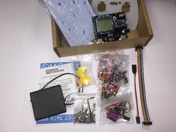
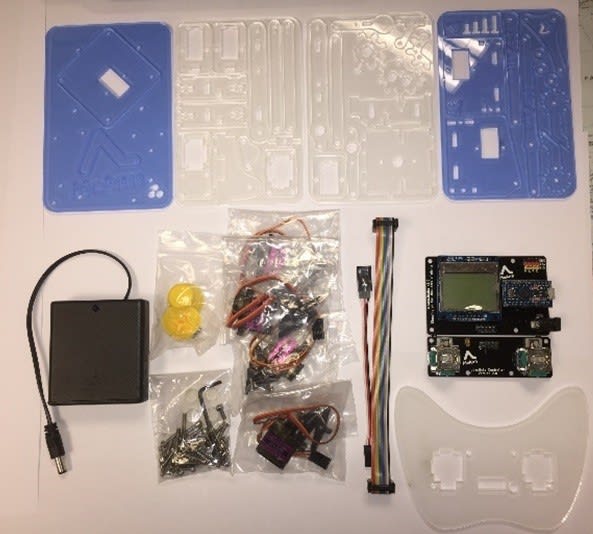
Unpacking the box: you can see all of the components contained in the kit.

Before starting the assembly, it is important to take off the plastic film from the acrylic parts as this will bind in the joints when assembled.
Also, do not over-tighten screws where permanent fixing is required as the screws tap a thread into the acrylic parts and could strip if over stressed. For the flexing fixings where movement has to take place between link, arm and gear pivots etc. these must be a loose fit where rotation is not restricted. It these are too tight then this will not allow for correct movement and operation, putting excessive loads on the servo motors.
There are 2 assembly guides attached to this post.
The Guide to Using the MeArm with Arduino gives good instructions with sketches and provides support for the build.
The MeArm Robot Assembly Guide gives a more pictorial view, links are included at the end of this article.
Starting with the joystick controller
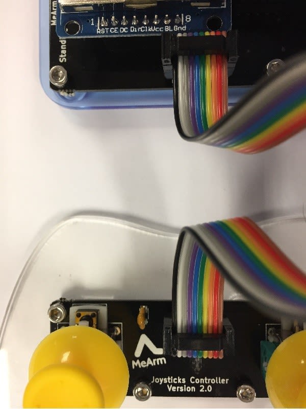
The joystick controller PCBs should be snapped off the main Arduino controller board. It is attached to the controller shaped acrylic plate using 4 x 6mm screws through the holes provided and threaded into the acrylic plate. It is then connected to the Arduino controller board using the 10 core ribbon cable assembly provided as shown in the images.
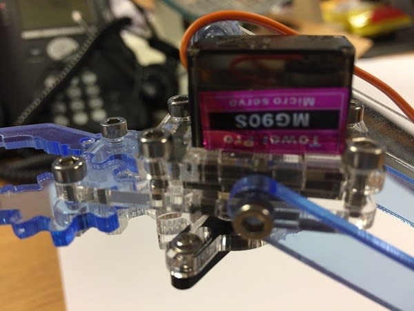
Servo motor calibration
It is worth marking the specific servo motor positions this will allow them to be calibrated from the controller board and also testing for correct operation when the individual subassemblies are built so that the arms do not interfere with the fixed parts. It is easy to adjust the actuator positions at this stage before going on to finalise the build.
| Controller connection | Motor position | Operation |
| M | Middle | Arm rotation |
| L | Left | Up / Down |
| R | Right | Forwards / Backwards |
| C | Claw / Gripper | Open / Close |
Note: the servo wire colouring differed to the controller markings in our kit, so the below data will show how to connect if needed:
| Servo wiring colours | Servo wires | Board |
| PWM Signal | Orange | Yellow |
| +6V | Red | Red |
| GND | Brown | Black |
You calibrate the motors by connecting to the controller board and powering this up. The motors will move to the respective positions, you can then mark a line on the shaft in line with the servo. The specific servo actuators and arms can be positioned in the orientation shown in the instructions.
Construction of the base
Pass the middle servo collar 3 over the servo motor using the cut out to pass over the wire. Attach the pivot servo plate 2 to the assembly using 2 x 8mm screws - refer to the sketches in the guide to using MeArm with Arduino.
Push 4 x 20mm screws through the arm base 1 from the underside. Put a nut onto each of these and spin partway down, then screw these into the servo plate 2 with the servo hanging down. Just tighten these screws flush into the servo plate then run the nuts down the screws to the arm base and secure.
Construction for left servo motor
Position the left arm servo into the servo collar 5, using the cut out to allow the wires to pass through. Pass the servo connector and slack wire through the rectangular hole in the collar. Secure using 2 x 8mm screws to the left arm servo plate 4.

Attach a black twin servo actuator to the long servo arm 6 using 2 of the self-tapping screws in the servo bag. Tighten snugly, but do not overtighten. Now position this on the left servo motor at approximately 9 o’clock. You can test this using the servo controller joystick for correct operation and that it will not interrupt with other components such as the base. The machine screw from the servo motor bag can then be inserted and tightened with a small cross point screwdriver.
Construction for the right servo
In the same way as for the left servo, install the right servo using collar 5, 2 x 8mm screws and the right arm servo plate 12. Attach a black twin servo actuator to the right servo arm base joint 13. Now attach this to the right servo motor at approximately 12 o’clock and secure with the respective machine screw. Operation can again be checked using the controller. Attach the parallel linkage 17 to the mounting at the top of the right arm servo plate 12 using a 6mm screw this needs to be free to move.
Construction for the Pig
This consists of using the left arm mount 8 and attaching the left arm base joint 10 and short arm 9 with a 10mm screw. This assembly should be free to move.
Construction of the arm bottom plate 14
We attach a black servo double actuator onto the arm bottom plate using 2 of the self-tapping screws in the servo bag.
These 5 sub-assemblies can be seen in the image below (clockwise from top left):
Image fixings and the screw size guide; left servo motor assembly; pig assembly; arm bottom plate assembly (note the servo motor shown attached here was just testing the fit using the claw servo, this bottom plate will eventually fit onto the middle servo already attached to the pivot plate); right servo assembly; base assembly.

Arm bottom assembly
We now bring together the left servo assembly with the front arm cross member, pig assembly, arm bottom plate and the rear arm base cross member.
Firstly, attach the front arm base cross member to the left arm servo plate 4 assembly using a 12mm screw and nut, the offset cut out in the cross member should be slightly closer to the left servo plate assembly. If these base screw and nut assemblies are not completely tightened, this allows for easier assembly of the bottom assembly with final tightening when the whole unit is complete.
Now position the pig assembly 8, carefully aligning the slots and use a 12mm screw through the servo arm 6, then through a parallel link 17, add a spacer 20 and screw into the short arm 9 (already on the pig assembly). After doing this I noticed that the servo arm was slightly offset in relation to the servo motor. I subsequently swapped the spacer using a couple of smaller washers giving an offset of about half of that from the original. The arm then ran true to the motor.
The arm bottom plate 14 is inserted at an angle into the left arm servo plate and levered onto the selector tabs on the pig. This is aided by ensuring that the 12mm screw fixing used earlier is a loose fit.
The back arm base cross member 11 can now be worked in to lock the pig assembly and held with another 12mm screw and nut.
This next stage involves bringing the left and right assemblies together. Firstly, attach the main arm cross web 15 to the left arm base joint 10 fixing with a 12mm screw and nut. This cross web can now be attached to the right arm base joint 13 as the arms are brought together, again use a 12mm screw and nut.
Finally, with careful adjustment the right arm servo plate 12 assembly can be aligned and fixed to the arm bottom plate 14 and the front and back arm base cross members 7 and 11. Slackening the existing 12mm fixings helps and it then fits a treat. Finally, use 2 12mm screws and nuts to secure this right servo plate. All of the fixings can now be tightened and the lower assembly is complete. The 12mm screw and nut assembly was best performed by first inserting the screw and then putting the nut into the slot in the cross members and holding with thumb and 1st finger. The screw can then be aligned and turned to engage using your other hand.


This assembly can now be attached to the base assembly middle servo motor.
The servo should have been calibrated by connecting to the controller board and powering up. The assembly should be aligned to approximately 12 o’clock with the MeArm base wording the correct way up. Attach to the servo using a machine screw supplied with the motor using a small cross head screwdriver. You can now power up the controller and check for correct operation with the joystick. Any slight adjustments are easy to do at this stage.
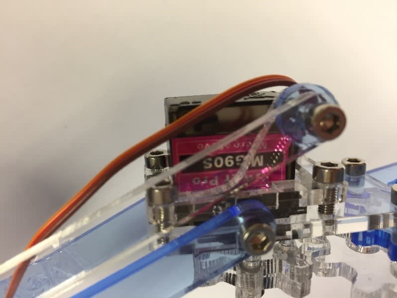
Next, attach the left longer wrist joint 16 end nearest the mid hole to the parallel linkage 17 already on the base assembly. Attach the off centre hole to the top of the left arm base joint 10, using 6mm screws for both of these.
On the right side using the parallel linkage connector 19, secure to the right wrist joint and to the parallel linkage connector with a 10mm screw. Attach the parallel linkage 17 from the right servo plate using a 10mm screw and spacer 20. Attach a new parallel linkage connector 17 to the parallel linkage connector 19 using a 6mm screw.

Image shows Assembly of the parallel linkage connector
Assembly of the gripper claw unit
Slide the clamp top servo collar 21 over the servo motor.
Carefully position the right wrist attachment 23 and the left wrist attachment 22 to the sides of the servo and position the clamp bottom servo mount 24 over these and the servo.
Now clamp together using 4 x 8mm screws threading into the clamp bottom servo mount.
Attach the left gripper 28 using an 8mm screw into the gripper plate 25, also put a 12mm screw in to keep this unit in place, but do not tighten yet.
Attach the single servo actuator arm onto the top servo gear 30 using a single self-tapping screw (from the servo fixing pack) into the long slot.
Attach to the calibrated claw servo, the servo arm should point to the 6 o’clock position with the gripper at the 12 o’clock position. (When assembled it is easy to test the gripper action using the controller and adjust the positions for optimum gripper movement).
Connect the bottom servo gear 29 using 6mm screws.
Now attach the gripper gear 26 using an 8mm screw from the underside and also screw in the 12mm screw which was already put into position earlier.
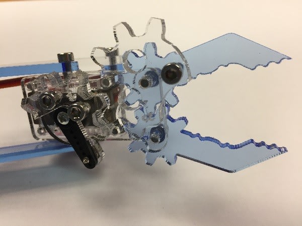
The jaws should be set to open at 90 degrees when meshed with the calibrated servo gear.
Now, before finally tightening the unit it is best to test the operation using the controller. I made some adjustments to the positioning on the servo which optimised the operation.
The finished gripping assembly can now be joined to the arm unit.
Firstly attach the gripper to the right wrist joint 31 using an 8mm screw into the right wrist attachment 23. (The drawings in the assembly guide show the exact positioning.)
Next, attach the parallel linkage 17 to the right wrist attachment 23 upper point with an 8mm screw and include a spacer 20 to correctly align the arm.
Finally, the left wrist joint 16 is attached to the left wrist attachment 22 using an 8mm screw.
The servo claw cable should be threaded through the cut outs in the main cross web 15 and then the extension cable supplied should be attached so that it can reach the Arduino controller board. Ensure that the correct connections are maintained.
The Arduino controller board can now be attached to the base plate 1 using the 4 mounting holes and spacer nuts.
All of the servo cables can now be finally attached to the Arduino controller board.
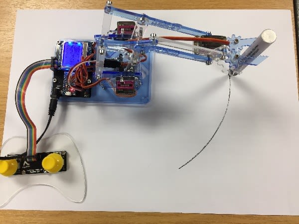
You are ready to go.
On power up the servos move to the calibrated points and then you are free to move the arm using the joystick controllers.
The Right control does up and down movement plus opens and closes the claw, with the Left control doing forward motion and backward motion, plus anti-clockwise and clockwise rotation.
With a little practice, it was easy to pick up various objects and move them around. The joysticks certainly allowed operation to be quickly and easily explored.
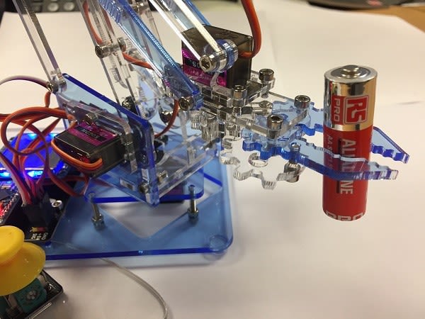
Overall, an impressive performance from a nice compact arm. Going forward you could program the controller to do some specific movements as required and even integrate it into custom designs and projects.