An Edge Compute IIoT Demonstrator Part 2: Custom Signal Conditioning
Follow articleHow do you feel about this article? Help us to provide better content for you.
Thank you! Your feedback has been received.
There was a problem submitting your feedback, please try again later.
What do you think of this article?
Building an envelope detector to clean up the signal from a piezoelectric vibration sensor
Introduction
In part one of this series my colleague introduced the Edge Compute IIoT demonstrator project and covered the hardware components involved in the build. In this post, we’ll take a look at how to signal condition the output from a piezoelectric vibration sensor to be sampled by an analogue input module.
What is an Envelope Detector?
An envelope detector (often called a peak detector) is a circuit that takes a higher frequency input signal and outputs the “envelope”, or the shape, of a given waveform. This circuit is most widely used in amplitude modulation radio receivers to demodulate the incoming high-frequency carrier signal.
Envelope detectors are also often used in musical applications to control other circuits such as a compressor, filters and noise gates. The high-frequency AM carrier is instead replaced with a signal in the audible range, and the detector forms part of a “side-chain” which describes parts of the incoming signal — in this case, the volume.
Fundamentally, an envelope detector is a simple circuit consisting of nothing more than a diode, resistor and capacitor. The diode serves to rectify the incoming AC waveform to be stored in the capacitor and the resistor serves to change the decay rate of the stored charge, which forms a filter network.
This circuit has some drawbacks including the low input impedance (which becomes problematic when connecting to a device or circuit with a high output impedance), and the voltage drop introduced by the diode which is unavoidable and means that the envelope of the input signal is not followed as accurately.
An improvement upon the simpler circuit is to utilise an arrangement called a “precision rectifier” which consists of an operational amplifier with a diode and resistor connected to the output. This circuit again has drawbacks and is further improved with the addition of another diode and resistor.
One limitation of this circuit is usage at high frequencies due to the slew rate (the rate at how quickly the output can change) of an op-amp, although with careful component choices an error of sub-1% at 100kHz is achievable. In our specific application, this would not be a concern if we did opt to use this circuit, as the frequency range we’re interested in is sub-20Hz.
Designing the Envelope Detector
Due to the low sample rate that the Brainboxes ED-549 analogue input module is capable of, we settled on using an envelope detector that would sample and retain the signal amplitude throughout the sampling period.
The first step was to take a look at the typical output of the vibration sensor (893-7281) with the conveyor belt in motion. As the sensor is supplied with 24Vdc the output voltage range has the potential to be above the +/-10Vdc range of the analogue input module, meaning at least some form of input conditioning will be necessary to clamp the signal.
The above oscilloscope plot shows the output of the sensor (the blue trace) which shows a low-frequency vibration where the motor and gearbox assembly have some “wiggle”, with a higher frequency vibration superimposed on top — most likely resulting from the high rotational speed of the brushed DC motor.
Peak-to-peak amplitude is on the order of 6.5-7V with a frequency of around 5Hz which is suitable for feeding into an envelope detector. With all this information to hand, we moved on to simulating the circuit.
The envelope follower circuit design consists of a minimal number of components, including one op-amp, a diode and a handful of passive components. By default, LTspice does not include the op-amp we planned to use (a TL071) so we picked one that was close to the same specifications.
As the vibration sensor has a high output impedance the TL071 is configured as a voltage follower which provides a higher output current to drive into the capacitor. A potentiometer is included after the diode to provide adjustable damping on the envelope rise, and another is included in series with a one-megohm resistor to control the decay.
Thanks to the high input impedance of the ED-549 analogue input module, which is specified to be greater than ten megohms, an additional voltage follower to buffer the output is unnecessary.
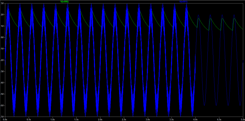
A mock-up input signal was created that roughly matched what was originally observed, and then we observed the simulation result which behaved as expected. Adjusting the resistor values for damping and decay changed the way the output voltage followed the input.
Assembling the Envelope Detector
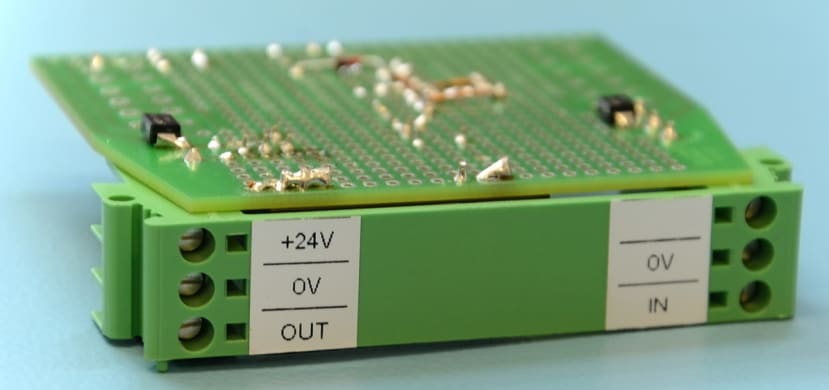
The first step in assembling the envelope detector was to select a suitable enclosure. As our demonstrator features a number of DIN rail-mounted components this was an obvious choice, and we settled on the Phoenix Contact UEGM 25 (648-3568) which includes six screw terminals.
Phoenix Contact also includes a PCB which fits the enclosure and features a layout similar to Veroboard. This made the layout of the circuit quicker as we did not have to wait for a custom PCB to be manufactured.
We started by placing components on the PCB to get a feel for the best placement and orientation. On the board are areas that appear purpose designed to hold a DIP package with two rails running through the middle, and we opted to use one of these areas to hold the op-amp.
An isolated DC-DC converter (235-1360) that provides a +/-12V supply from a single 9-36Vdc input was chosen for the op-amp power supply, and this was by far the largest component on the board. What would’ve otherwise remained as unused space behind the front panel was occupied by the converter, as this was the only suitable place the module would fit and be easy to connect to the rest of the circuit.
Phoenix Contact also provides a PDF that includes the layout of the PCB, which we loaded into Inkscape to help with planning out the wiring. A colour code was used mainly to aid with power supply routing, as routing signals was far easier thanks to the limited number of connections to be made.
The op-amp was also placed onto the wiring plan to ensure that all the pins would land in the right places and to be used as an aid when soldering to check connections. Where necessary, enamelled copper wire was used to jumper to connect various pins. This was mostly fitted on the rear of the PCB due to the limited number of connections available around the DIP socket — commonly restricted to one soldered connection alongside the socket pins due to the layout of the board.
Supporting components including decoupling capacitors, TVS diodes and the all-important resistors, rectifier diode and capacitor were installed to complete the envelope detector. A “smoke test” was conducted using a current-limited bench power supply without the op-amp installed, and voltage rails were checked to ensure they were correct and stable.
Testing
With all the voltage rails good and appearing in the right places the op-amp was installed and another smoke test was conducted. The circuit behaved as expected with no unusual smells, heat or excessive current consumption.
Initial tests were performed with a function generator connected to the circuit input to avoid risking damaging the vibration sensor should any malfunctions happen. An oscilloscope was also connected to the input (blue trace) and output (yellow trace) of the circuit so the response could be observed.
With the circuit verified the vibration sensor was then connected to the input, and the same tests were repeated. Much to our delight, the circuit performed perfectly, and the resulting oscilloscope waveform matched well with what was observed during the simulation.
To finish the box labels were printed that identify the screw terminals, trimmed to size and then stuck in place. Space was freed up on the DIN rail by removing a number of stops and then the envelope detector snapped into place, wired into the ED-549 module and tested once more.
To Finish
In this article, we’ve taken a look at what an envelope detector is and the theory of operation. We’ve then designed, simulated, implemented and then tested our own detector based around a TL071 operational amplifier. We’ve also shown the importance of simulating a circuit, especially one designed to condition a signal, to check that it performs correctly before committing to a full printed circuit board layout.
The third and final article in this series will take a look at the software which will drive the demonstrator.


