An Edge Compute IIoT Demonstrator Part 1: Hardware
Follow article
 Dave from DesignSpark
How do you feel about this article? Help us to provide better content for you.
Dave from DesignSpark
Thank you! Your feedback has been received.
Dave from DesignSpark
There was a problem submitting your feedback, please try again later.
Dave from DesignSpark
What do you think of this article?
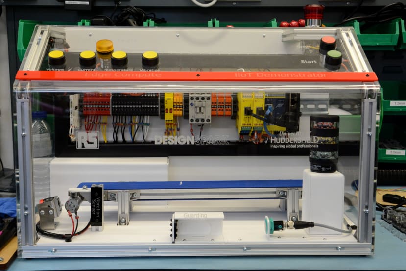
Compact demo platform showcases how edge compute can be integrated with industrial processes for Industrial Internet of Things (IIoT) enablement.
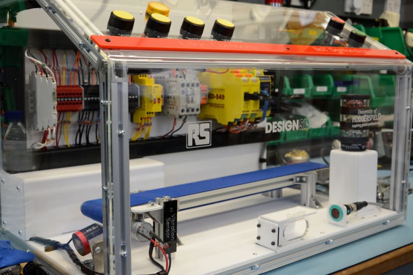
The Centre for Industrial Analytics (CIndA) at The University of Huddersfield and DesignSpark are working together to create a self-contained IIoT hardware platform which integrates a selection of typical sensors and outputs, along with edge compute and industrial I/O, and which will be used in both demonstrations and student projects.
In this article, we take a look at the overall operation and platform hardware configuration.
Process
The industrial process is comprised of a miniature conveyor belt controlled by start (479-3582) and stop (479-3633) buttons. However, as we’ll come to see, this could easily be expanded upon in future via the edge compute capability, in order to enable much more advanced control, along with integration with other systems.
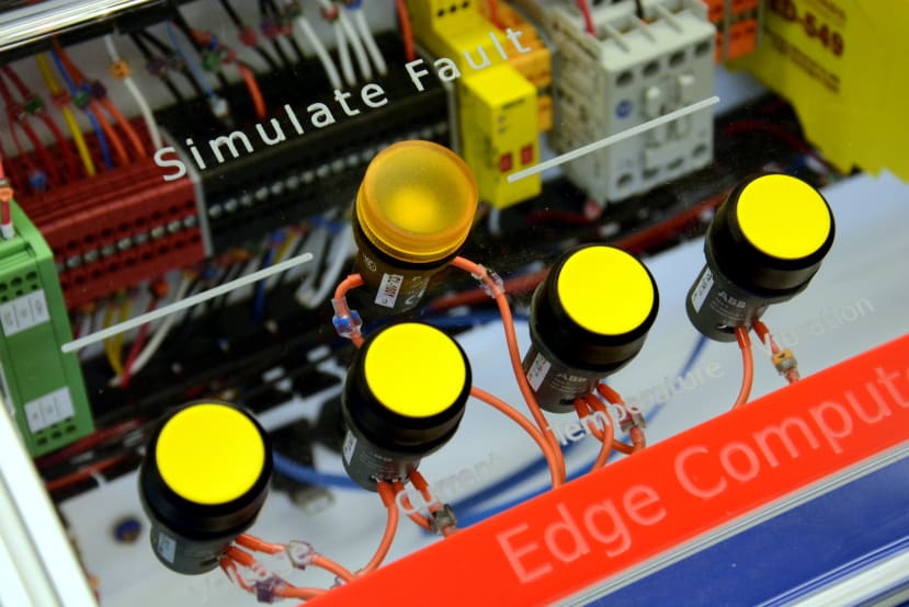
There are buttons to simulate conveyor motor voltage, current, temperature and vibration faults (479-3661) . Simulated faults may also be remotely injected via the edge compute; while not typically desirable in a real-world application, this could prove particularly useful in an educational environment, and in R&D where it may be just one subsystem within a larger research platform.
Safety
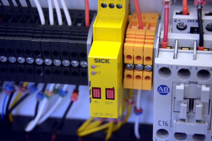
A dual-channel safety relay (701-9216) is used at the heart of the safety system.
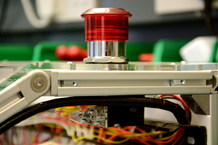
The first channel is connected to an emergency stop (e-Stop) solution, comprised of an Allen Bradley 800T Series SPDT contact block (183-4463) plus e-Stop stop push button (183-4521) .
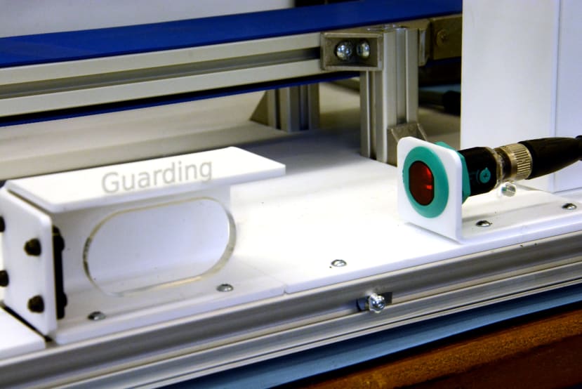
The second channel of the safety relay is connected to a Pepperl + Fuchs diffuse photoelectric sensor (228-992), which may be triggered via an aperture in the demonstrator enclosure front.
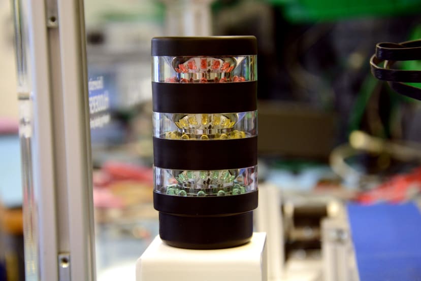
Finally, there is a Banner TL50BL Red/Green/Yellow Signal Tower (865-5093) to provide a clear indication of machinery operational status.
Edge Compute and I/O
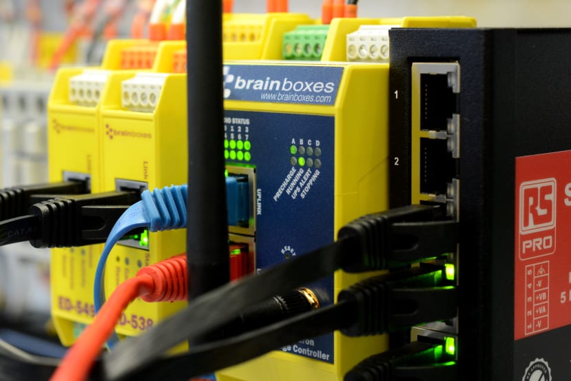
A Brainboxes BB-400 NeuronEdge Controller (181-7467) is used for process control and edge compute. This is based upon a Raspberry Pi compute module and integrates industrial I/O and a UPS into a convenient DIN rail-mounted form factor. The BB-400 runs a Linux operating system and features an easy-to-use web interface for configuration, plus out-of-the-box support for Node-RED and running Docker containers. Applications can be developed using pretty much any programming language or framework that is available for Linux.
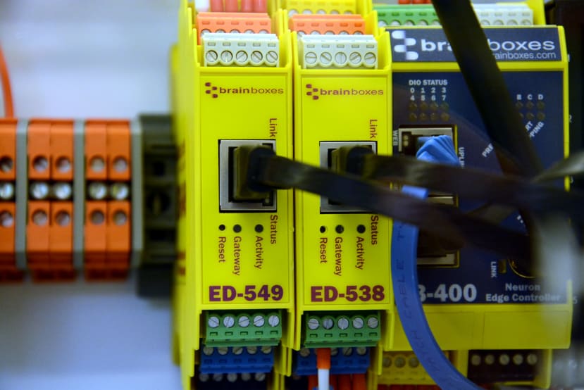
The BB-400 has 8 digital I/O lines and these are expanded upon via an Ethernet-connected Brainboxes ED-538 (789-8144) , which provides an additional 8 non-isolated digital input channels, along with 4 digital relay output channels.
Analogue inputs are also required for measuring supply voltage and current, plus motor vibration. A Brainboxes ED-549 (847-4743) is used to provide 8 analogue inputs and this is also integrated with the BB-400 via Ethernet.
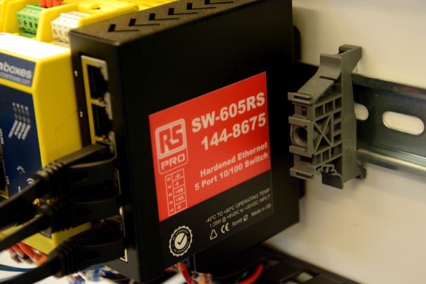
The BB-400 and I/O modules are all connected to an RS Pro DIN rail mount 5-port 10/100 Ethernet switch (144-8675) , forming a private LAN for industrial I/O. The BB-400 also has a second “uplink” Ethernet port, which by default is isolated from the LAN port and can be used for configuration, diagnostics and connecting to a remote cloud platform. This is cabled to an RJ45 socket mounted on the enclosure rear panel. In addition to this the BB-400 also features integrated WLAN which can be configured as either an access point or Wi-Fi client, and used for similar purposes.
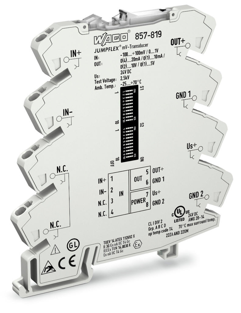
A Wago Signal Conditioner (135-7396) is used to amplify the 0-50mV signal level signal provided by the DC shunt (810-3261) which is used for current measurement, following which this is fed into a channel on the ED-549 that is configured for 0-10v input.
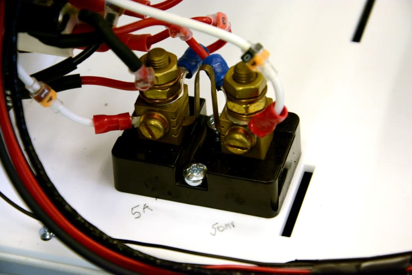
Current measurement DC shunt.
Sensors
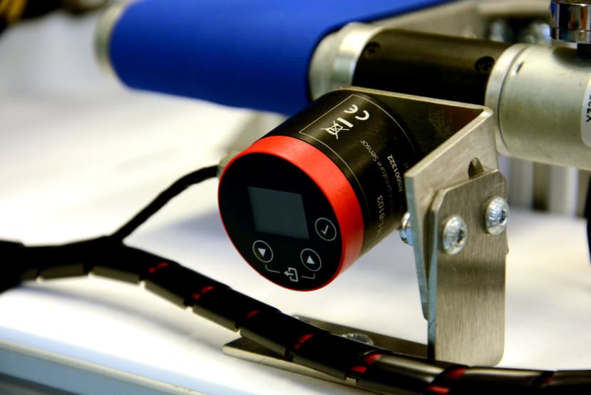
An RS Pro voltage output signal infrared thermometer (161-8103) is used to measure gearbox temperature. This provides measurement over a range of 0-1,000C and can be configured for 0-5v, 1-5v or 0-10v DC output. The thermometer also features an integrated OLED screen for local display and configuration and is secured in place via the optional mounting bracket (905-8777) .
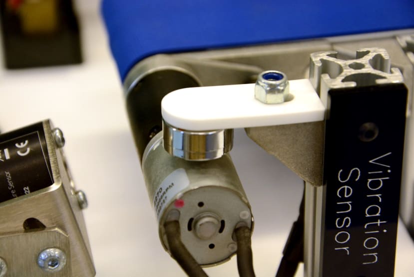
A TE Connectivity CM-01B Contact Microphone (893-7281) is used to measure motor vibration. The piezo sensor provides a buffered output of up to 30v and so as to avoid the need for a high sampling rate, the signal output will first be conditioned using a custom envelope follower circuit, before being fed into the ED-549. This will have the effect of holding the amplitude peaks for some time in order that they can be measured. A future improvement could be to replace or augment the signal conditioning with hardware that additionally carries out spectrum analysis.
Next steps
In Part 2 of this series, a colleague will be covering the design, implementation and testing of the custom signal processing, which will be built into a DIN rail-mounted prototyping enclosure.