Air Quality Kit - Mobile Air Conditioner: Part 2
Follow article Dave from DesignSpark
How do you feel about this article? Help us to provide better content for you.
Dave from DesignSpark
Thank you! Your feedback has been received.
Dave from DesignSpark
There was a problem submitting your feedback, please try again later.
Dave from DesignSpark
What do you think of this article?
In the previous chapter, I shared how to get data from Air Quality Kit to Arduino Nano 33 IOT. So, in this chapter, I will focus on the air conditioning part in depth. How to do it? How does it work?
Unlike traditional air conditioners, I’m not using the compressor and expansion values to transfer heat to the refrigerant to become a cycle. I'm using semiconductor chilling refrigeration for refrigeration; it can be smaller and more efficient, but at the same time, the coverage that uses semiconductor chilling is even smaller.

Then, let me introduce how the semiconductor chilling makes air conditioning. Below is the prototype of the air conditioning. First, there have a semiconductor chilling in the middle of the air conditioning, which is the main component of this air conditioner. For the semiconductor chilling, there are two sides, one is the cold side, and another is the hot side. For the cold, I put a heatsink and a fan on top of it to conduct the cold outside. And then, I also added a water pump, and another heatsink below the hot side to cool down the semiconductor chilling. Using the water pump and the heatsink to cool down the semiconductor, chilling can protect the semiconductor and it can obtain higher efficiency.

As I mentioned before, the semiconductor chilling has two sides, one is the cold side, and another is the hot side. The reason why the semiconductor chilling can be refrigerated is because of the Peltier effect. When the electronic passed through the thermocouple, heat is evolved at one junction and is absorbed in the other junction. The Peltier effect is the presence of heating or cooling at an electrified junction of two different conductors. For more information, you can search for the Peltier effect or semiconductor chilling.

After we make this air conditioner, let's move back to how to trigger it on and off. As I said in the previous chapter, the main objective of this project is to use electricity correctly and solve the global warming issues. That is why we need the air quality kit to get the environment temperature to determine if we need to turn on the mobile air conditioner.
First, after we receive the data in the MCU, we need to set up some conditions to trigger the air conditioner. (If you don’t know how to receive the data in the MCU, you can read the previous chapter first.)
void Chilling()
{
  if (thv_temperature >= 30 ){
     digitalWrite(2,HIGH);
    }
  }else{
    digitalWrite(2,LOW);
  }
  delay(1000);
}
As the power consumption of both the semiconductor chilling, fans, and water pump is 12V DC. Therefore, we need to add a relay and an external power supply (you can use the bench power supply, lead acid battery, or any other battery that is 12V DC.) between the MCU and the air conditioner. Below is the prototype of the connection.

Then our air conditioner work will work with the air quality kit.
However, as I mentioned in Part 1, by not using electricity is not the most effective way to solve global warming, it may lead to the risk of some chronic diseases and heat stroke. So after I made this air conditioner, I thought about how to make it more effective and save power. Hence, I try to use PWM to drive the air conditioner to reduce power.
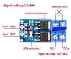
However, a relay is not the most suitable way for us to control it via PWM. So, I changed the relay to a MOSFET switch. By using MOSFETs, we can control it via PWM. It is important to note that most MOSFETs have their own operating voltage, output capacity, and trigger source limitations. So, we need to choose a suitable MOSFET module or component.
Inverter air conditioner
First of all, I added a thermal sensor to the top of the heatsink (on the cold side) to see the efficacy of the air conditioner.

Prototype

Thermal Sensor


void ChillingTherrmometer()
{
  VRT = analogRead(A2);              //Acquisition analog value of VRT
  VRT = (3.30 / 1023.00) * VRT;      //Conversion to voltage
  VR = VCC - VRT;
  RT = VRT / (VR / R);               //Resistance of RT

  ln = log(RT / RT0);
  TX = (1 / ((ln / B) + (1 / T0))); //Temperature from thermistor

  TX = TX - 273.15;                 //Conversion to Celsius
}
To make an efficacy inverter air conditioner, we must first do an experiment to see the efficiency of the air conditioner under different PWM.

In the graph above, we can obtain the minimum limit for the air conditioner at different duty cycles. After reaching the lowest point, the air conditioner temperature will remain stable.
|
Duty Cycle |
Stable temperature |
Power |
|---|---|---|
|
100% |
~27 |
~25W |
|
80% |
~25 |
~17.2W |
|
70% |
~23 |
~13.7W |
Then, as we can see the temperature will remain stable at last, no matter what the power remains unchanged, which means there must have energy lost. Hence, I was thinking about if I let the air conditioner adjust the PWM when it achieves a specific temperature which is used to avoid energy loss. Therefore, If I set the temperature of the heat sink to be lower than 25, then the PWM adjust to 80%. And if the temperature of the heat sink to be lower than 22, then the PWM adjusts to 70%.
void Chilling()
{
  ChillingTherrmometer();
  Serial.print("Temperature: ");  Serial.print(thv_temperature);
  if (thv_temperature >= 30 ){
    if (TX >= 25){
      analogWrite(2, 255);    //100% duty cycle 255
      Serial.print(" Heat sink temperature: ");
      Serial.print(TX);
      Serial.print("°C  ");
      Serial.print("100% duty cycle");
    }else if (TX >= 22 && TX < 25){
      analogWrite(2, 204);    //80% duty cycle 204
      Serial.print(" Heat sink temperature: ");
      Serial.print(TX);
      Serial.print("°C  ");
      Serial.print("80% duty cycle");
    }else if (TX < 22){
      analogWrite(2, 178);    //70% duty cycle 178
      Serial.print(" Heat sink temperature: ");
      Serial.print(TX);
      Serial.print("°C  ");
      Serial.print("70% duty cycle");
    }
  }else{
    digitalWrite(2,LOW);    //Shut down
    Serial.print("Temperature < 30");
  }
    delay(1000);
    Serial.println();
}
Finally, I get the red curve below. We can see that after the red curve hits 25, the temperature will continue to drop. And after reaching the lowest point, it will remain between 22-25, but will increase slowly. If the temperature is hotter than 25 again, the PWM will change to a 100% duty cycle.

The result is what I expected, and I am very happy with the result. Under the air quality kit, we can determine when the air conditioner needs to be turned on, which is an effective way for us to turn on the air conditioner and prevent some chronic diseases and the risk of heat stroke. At the same time, the inverter air conditioning system has low power consumption and higher efficiency.
Finally, thank you for reading this series of articles about Air Quality Kit - Mobile Air Conditioner, I hope you enjoy it.