Adafruit’s awesome Arduino compatible Adalogger
Follow article
 Dave from DesignSpark
How do you feel about this article? Help us to provide better content for you.
Dave from DesignSpark
Thank you! Your feedback has been received.
Dave from DesignSpark
There was a problem submitting your feedback, please try again later.
Dave from DesignSpark
What do you think of this article?
Compact ARM Cortex-M0 board for low-cost data logging
Adafruit Feather is a range of Arduino compatible development boards designed to be flexible, portable and light. Each share the same small form factor and include LED matrix displays, WiFi and LoRa modules and more. A comprehensive overview of the Feather boards can be found on the Adafruit website.
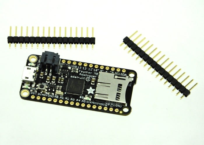
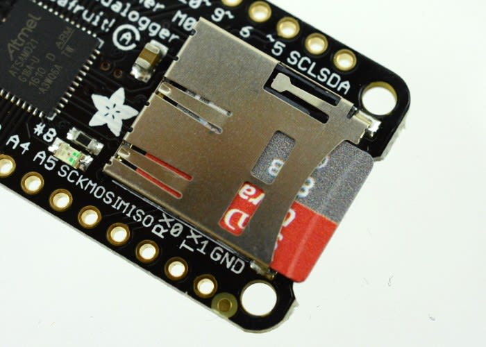
In this post we will take a look at the Adalogger – an all-in-one data logger – including on-board USB, a microSD card holder and even LiPo battery charging! We will get it up and running with the Arduino IDE, before connecting an Adafruit accelerometer board and logging some data.
Boards of a feather
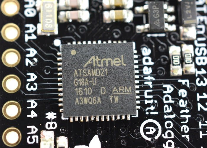
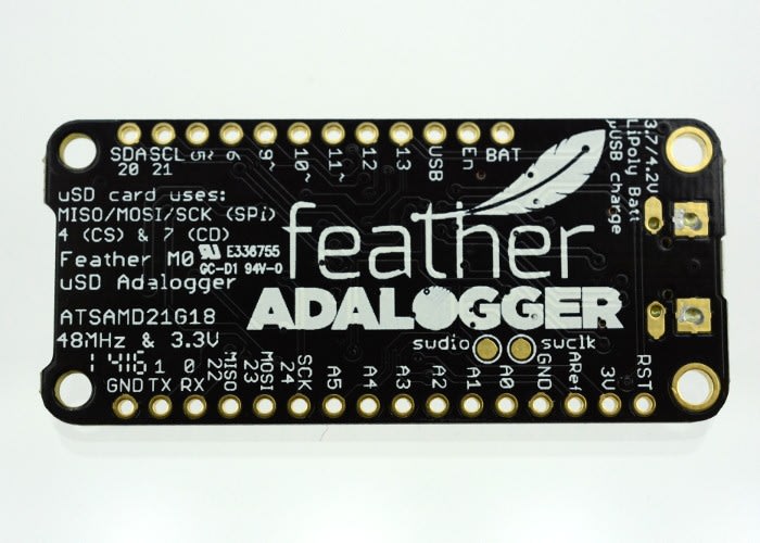
It should be noted that the Adalogger comes in two variants: one with an ATSAMD21G18 ARM Cortex-M0 microcontroller, the other with an ATmega32u4. For this post we will be using the Cortex-M0 version.
Before connecting any additional peripherals, let’s first get the Adalogger working with the Arduino IDE, so we can test out some demo code (or ‘sketch’, in Arduino parlance).
Firing up the latest version of the IDE (1.6.13 at the time of writing), we need to add a URL to the Additional Boards Manager before we can connect to the board. In the Preferences menu, locate the Additional Boards Manager option, and add the following URL:
https://adafruit.github.io/arduino-board-index/package_adafruit_index.json
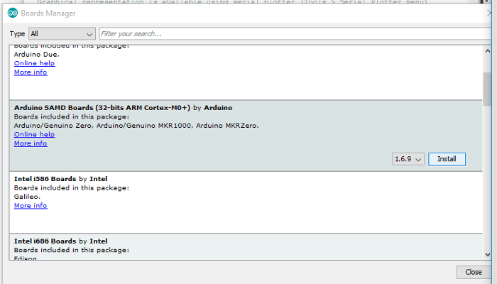
Click OK to save. Next, navigate to the Tools menu, then Board > Boards Manager. First, scroll down to find the Arduino SAMD Boards (32-bits ARM Cortex-M0+) by Arduino tab (a bit of a mouthful!) and install the latest version (1.6.9 at time of writing).Staying in the Boards Manager, navigate to the Adafruit SAMD Boards by Adafruit tab and install the latest version (1.0.13 at time of writing). Following this, it is best practice – though not strictly necessary – to quit and restart the Arduino IDE.If you are running Windows, you will need to download and install additional drivers from Adafruit, ensuring that you select ‘Feather M0’ during installation.
Now we can connect the Adalogger to our PC using a micro USB cable. The board automatically switches to USB power, so there is no need to flick a switch or set a jumper to the correct pin. The computer will recognise the device and create a COM port.
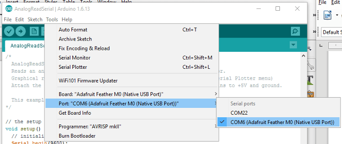
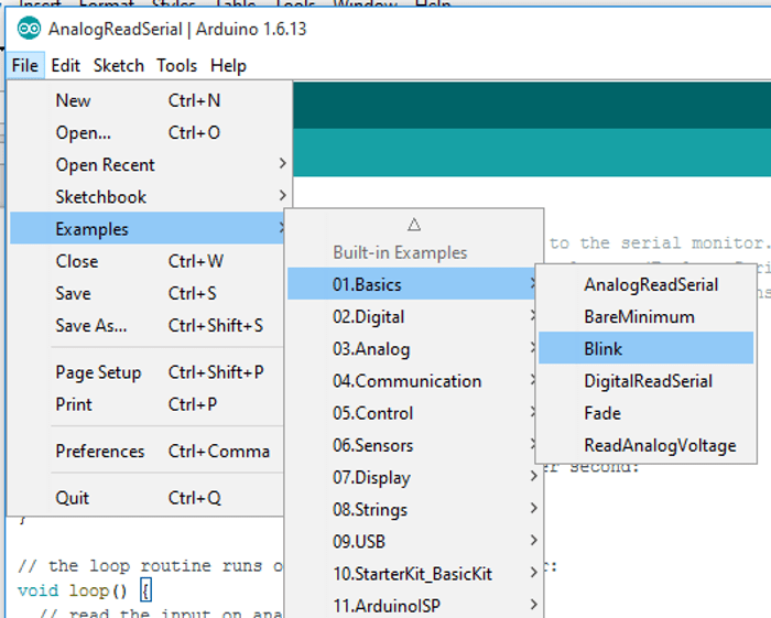
Heading to the Tools>Ports drop down menu should show the Adafruit Feather M0 assigned to a COM port. Select it, and you are ready to upload a demo sketch to the board. ‘Blink’, found in Files>Examples>Basics>Blink is a great place to start.
Open the sketch and try uploading it to the board. If the above steps were completed successfully and all goes well, you should see the onboard red LED blinking away.
Logging data to the SD card
Now that we know we can upload sketches to the Adalogger, let’s try to write some data to an SD card. Start by formatting the SD card with a FAT filesystem, I used the formatting tool found here.
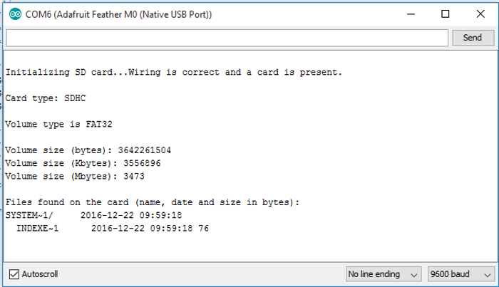
We will use an example sketch that comes bundled with the Arduino IDE to try to get some information about the card (and is a good basic test). Navigate to File>Examples>SD>CardInfo. Upload the sketch to the Adalogger, then open the serial console (by clicking the small ‘magnifying glass’ icon in the top right of the IDE). You should see something similar to the screenshot below:
Now we can try to write some data to the card. Again, there is an example sketch to do this that comes with the IDE, but there is a simpler version available on Adafruit’s GitHub. I took this code and modified it to read and log the voltage of a LiPo battery connected to the Adalogger. This functionality is built-in to the board, meaning we don’t have to worry about errors in our own wiring – simply the code working or not.
The example sketch can be found here.
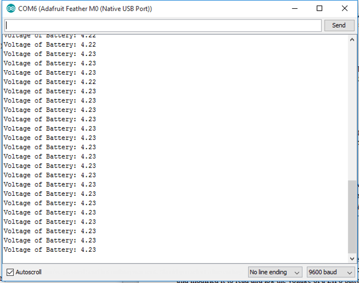
We can see the voltage being read and printed to the serial console, to check that the data was being written to the log file, I powered off the Adalogger, removed the SD card and put it into my PC, and opened the txt file. Alas, there were several txt files, but each was empty, with no data logged whatsoever!
A little digging in the Adafruit documentation shows that in fact the data is being stored in a buffer, and only written to file every 50 datapoints. Perhaps I had not been running the logging for long enough during testing to actually get any of my data saved! So I ran a longer test over several minutes, and checked again. I still had no data, so to force each data point to be saved, I added the line:
logfile.flush();
This solved the problem, though the Adafruit documentation advises that this will cause the Adalogger to draw roughly 3 times as much power, so this is not ideal for any low power applications.
Logging more interesting data
The Adafruit range includes lots of sensors and input devices mounted on small, handy breakout boards to make it easier for the hobbyist to get prototyping, especially with platforms such as the Raspberry Pi and Arduino.
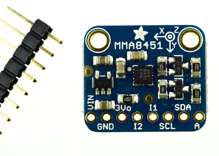
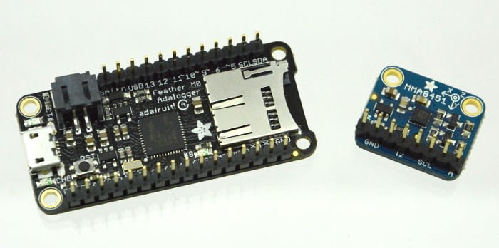
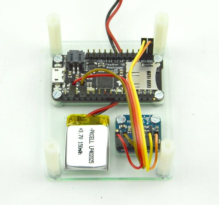
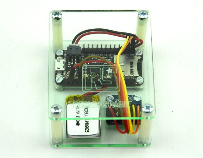
We will now connect one such module, a 3-axis accelerometer board that communicates via I2C to the Adalogger and start logging the values we can get from it. Connecting the two boards couldn’t be much simpler: after soldering on the header pins provided, we used four female-female jumper wires, connecting Vcc, GND, SCL and SDA.
Next, a simple mounting plate was designed and laser cut, to hold the boards and battery together. This helps to keep everything neat, and gives additional protection in case of stray wires / metal objects on the bench touching the pins on the underside of the boards.
As with all of the Adafruit products, the accelerometer breakout board comes with handy reference documentation and code to get you up and running. I had to download and install two libraries from the Adafruit GitHub: here and here before trying to get some data from the sensor.
A quick note on such libraries: it is well worth noting the value and importance of these libraries and breakout boards. Without them, using these sensors would be a lot harder, particularly for those who are learning or do not have experience with electronics. Even if we had the breakout board, without the library, all we would get from the sensor is numbers that would require further calculation to get more useful or sensible data. Adafruit strives to build their libraries so that their code provides data in SI units, which means we can focus on the project itself!
Further information on how to install libraries can be found here.
With these installed and the IDE restarted (again, good practice to ensure the libraries are installed and added correctly), I uploaded the example sketch (File>Examples>Adafruit MMA8451 Library>MMA8451 demo) onto the Adalogger to test that all was well.

I then simply grafted in parts of the example accelerometer sketch to our existing datalogging sketch, and soon had data from the accelerometer logging to the SD card.
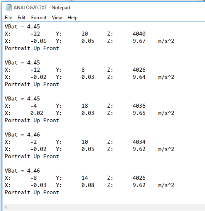
The final code is available here.
Summary
Adafruit’s range of Arduino compatible boards continues to expand and impress, as does it’s range of breakout boards and modules. Though they are aimed squarely at the hobbyist, education and maker markets, they are useful for anybody wanting to quickly prototype and build interesting projects.
Open design (Adafruit’s shares the board layout and schematics of most of it’s products) coupled with great documentation and software makes for a fantastic user experience, whilst an active online community fills in the gaps. With plenty of boards out in stores, and being used by people all over the world, Adafruit is certainly ticking plenty of boxes when it comes to enabling the maker and electronics project scene.