A Smarter Smart Home (Champion)
Follow article Dave from DesignSpark
How do you feel about this article? Help us to provide better content for you.
Dave from DesignSpark
Thank you! Your feedback has been received.
Dave from DesignSpark
There was a problem submitting your feedback, please try again later.
Dave from DesignSpark
What do you think of this article?
By Wen Chin, LO | Ki, CHEUNG
Home Automation, or “Smart Home Technology”, is very popular nowadays. It is the technology to control many aspects of your home through the Internet of Things (IoT). In this project, we develop a system to provide new functions to make your home automation even better!
This system provides four new functions:
Door automation: A RFID (Radio Frequency Identification) reader is installed near a door. When a person comes close to the door with an RFID tag, the reader can identify whether the person has the access right or not. If the person has the right, the door will automatically open (see Fig. 1).

Figure. 1
Light automation: A pair of infra-red sensors is installed near a door. When a person walks into a room from the door, the infra-red receiver is blocked and the light is on for the person (see Fig. 2). When the person walks out of the room, the infra-red receiver is blocked again and the light is off. Note that the case for the infra-red sensors is designed by using DesignSpark Mechanical (see Fig. 3). Moreover, some RGB LED light strips are designed to create warm lighting. It is controlled by a mobile app (it will be described later) through an Arduino IoT and BLE (Bluetooth Low Energy).


Figure. 2

Figure. 3
Mobile app: A mobile app is developed for users to remotely control different aspects of their home (see Fig. 4). There are five parts to the app. The first part is the door status. It shows whether the door is closed or not. The second part is the LED status in different rooms. “0” means off and “1” means on. The third part is the control of the LED status in different rooms. The fourth part is to show the status of the connections. It means it can show whether the smartphone is connecting to different devices or not. The fifth part is the notification. It can interact with users. For example, a notification of the message “Going to sleep?” is displayed when the door of the bedroom is closed and the pressure sensor on the bed is activated (see Fig. 5).

Figure. 4
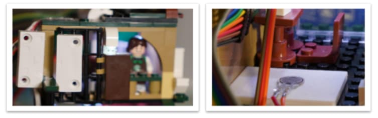
Figure. 5
Bus ETA (Estimated Time of Arrival) display: There is a motion sensor near the exit door (see Fig. 6(a)). When it detects a movement (i.e., the user is leaving home), it sends a signal to the microcontroller. Then the microcontroller sends the signal to the mobile app and the app checks events inside the calendar (e.g., “go to PolyU”) (see Fig. 6(b)). Then the mobile app access the government ETA website to get data and display ETA on an LCD screen (see Figs. 6(c) and 6(d)).


Figure. 6
The demonstration video is shown below.
Comment by judges: It is a very good application. It is practical and reasonable, especially the bus ETA display. Since this time the presentation is online, it is very difficult for candidates to demonstrate their phototypes or products properly. This team gives a very good presentation: they build a small toy house (it is made of building blocks) and implement all the features inside the house. Thus the presentation is very clear and all the features can be demonstrated very properly. Moreover, they make use of different cameras to show the status of different devices (sensors, the mobile app, and the LCD screen together) at the same time. The presentation shows the team has a very good team spirit. The product design is good and they spend quite a lot of time overcoming Bluetooth multicast communication problems. Finally, they can make use of PCB DesignSpark and 3D mechanical tools properly in the product design.