Molded or Formed parts need a minimum draft to allow parts to extract from shaping tools such as plastic injection molds, pressure / gravity die castings, formed metal pressed sheets. Understanding and being able to design using the necessary draft angle is part of being an Industrial designer or anyone involved in specifying manufacturing information.
Either analyse your own designs or Import supplier models and check the draft before commiting to any manufacture.
DesignSpark Mechanical has a draft dynamic analysis tool in the Measure Tab and I think it's superb.
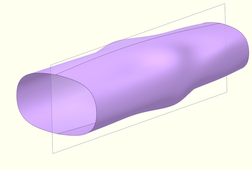
Example part:
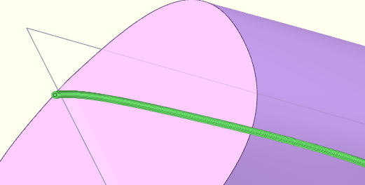
Tube of varing profiles made by blending layout constrained sketches to tangential (red face) and conic 2.5 draft angled face. (blue face).
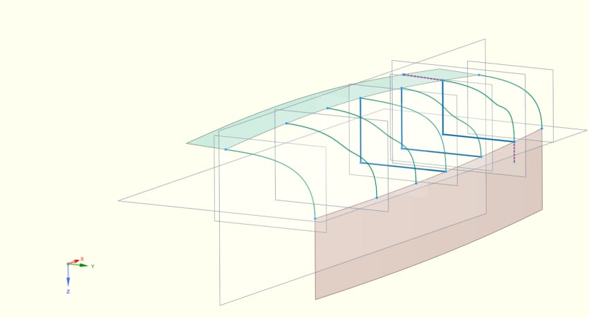
Using the new Mirror tool or duplicating the curves to make a continuous section, other faces can be made.
Analysis can be made on a singular face or the complete shape.
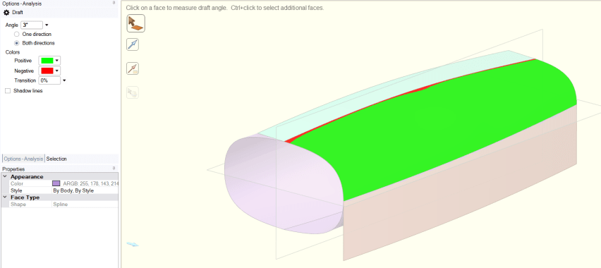
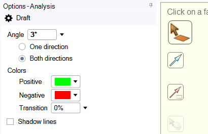
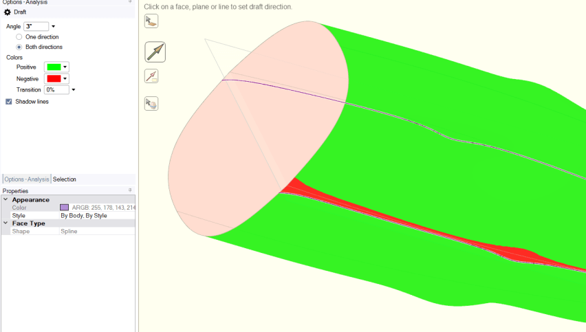
For example, the draft has been set at 3 degrees; with the direction of draft specified using this arrow:

and choosing the plane shown, a white arrow direction is drawn ( see 2nd above image - arrow in left hand bottom corner).
With 'Both directions' also selected, any face about the specified direction that is not at least 3 degrees will be shown in the user specified or default color - here shown in red.

The part was designed with 2.5 draft.
Changing the check value to 2.51 the result is shown below.

Changing the check value to 2.5 the result is shown below.

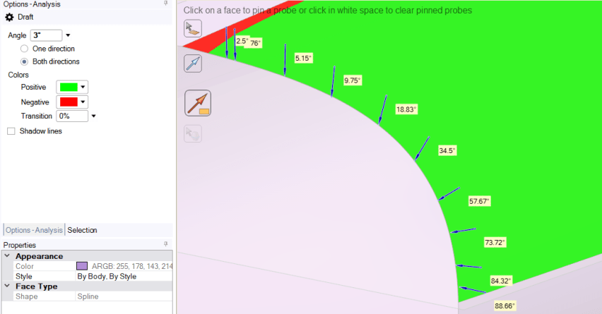
Probing can be singular or multiple points:
Transition values will show the gradient of draft. With 1 % transition from a 2.5 degree start, all areas upto 2.58 degrees are shown in red.

Draft angle dynamic dragging:

Whole part analysis.

Shadow Lines can be shown and created:( rename as appropriate ) Shown is a 3 degree shadow line.

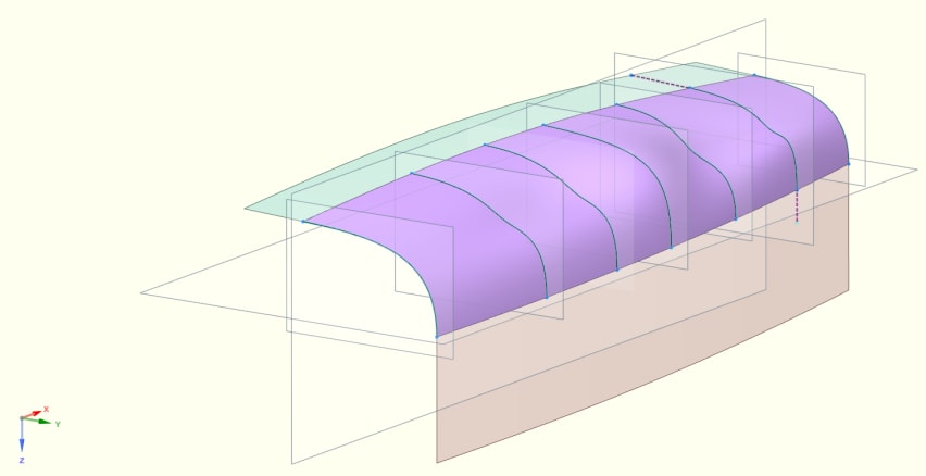
Enhanced shaed part with drafting plane.
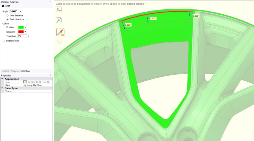
In the design of a Diecast car wheel shown below, the model creator ( me ) forgot to add draft to the wheel rim - whoops!

Manufacturing errors created by inadaquate design; even even small ones, cost time and money to fix and reputation is lost!
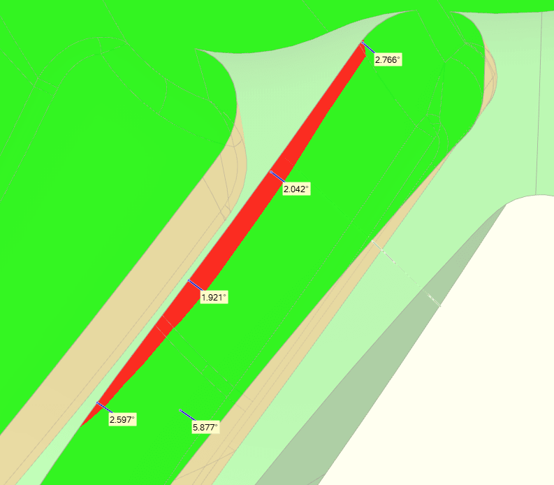
On the wheels rear, all the ribs that create the hollows also need the draft checking. The part will shrink during molding and may shrink tight on any inadquately drafted faces causing part ejection problems.
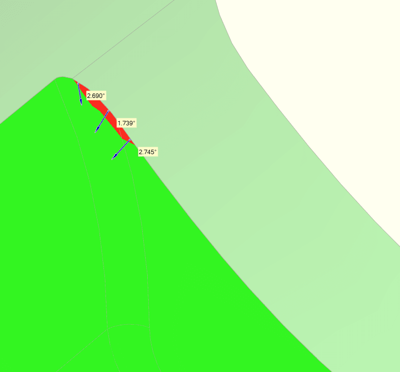
Again , there are more small area's that are less than 3 degrees. ( 3 degrees isn't the standard for diecast - it will depend upon material and texture ( texture not usually applied to diecast parts) - advice is to always seek experienced manufacturer advice).

Finding small areas like this would be impossible without an analysis tool:
Ask if wanting additional information.