THE MIXED DOMAIN OSCILLOSCOPE: HOW IT WORKS
Follow article
 Dave from DesignSpark
How do you feel about this article? Help us to provide better content for you.
Dave from DesignSpark
Thank you! Your feedback has been received.
Dave from DesignSpark
There was a problem submitting your feedback, please try again later.
Dave from DesignSpark
What do you think of this article?
In new designs, the level of integration among processors, sensors, and communications has increased, blurring the traditional lines between analog, digital, RF and power system design. Wireless technology is transforming the way engineers need to innovate, design, debug and troubleshoot. Prior to the invention of the mixed domain oscilloscope there was no single instrument optimized for these types of measurements. This technology brief explains how a mixed domain oscilloscope (MDO) combines the technology of a state-of-the-art mixed signal oscilloscope with spectrum analyzer hardware and software to provide a complete set of capabilities for measuring your highly-integrated designs.
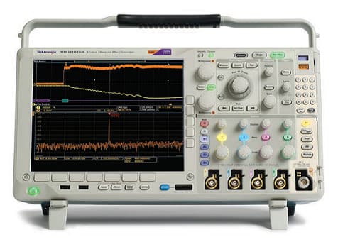
MDO4000B Series Mixed Domain Oscilloscopes

What is an MDO?
Traditionally, three different instruments were needed to make analog, digital and RF measurements:
- The oscilloscope, for making time-correlated measurements on analog signals in the time domain;
- The logic analyzer, for making time-correlated measurements on digital signals in the time domain. A mixed signal oscilloscope (MSO) is an oscilloscope with additional digital channels;
- The spectrum analyzer, for making measurements on RF signals in the frequency domain.
- 2 or 4 analog time-domain channels with 100 MHz, 200 MHz, 350 MHz, 500 MHz or 1 GHz of bandwidth, with serial bus decode and triggering capability;
- 16 digital time-domain channels with timing resolution down to 60.6 ps, with serial bus decode and triggering capability;
- 1 spectrum analyzer channel with either a 3 GHz or a 6 GHz input frequency range.
Most oscilloscopes have the capability of calculating and displaying a Fast Fourier Transform (FFT) of the acquired time domain signal. However, an MDO has major advantages when compared against a typical oscilloscope with FFT capability:
- Superior capability and fidelity for frequency domain measurements;
- Independent acquisition systems enable optimal views in both the time and frequency domains;
- Spectrum measurement capabilities.
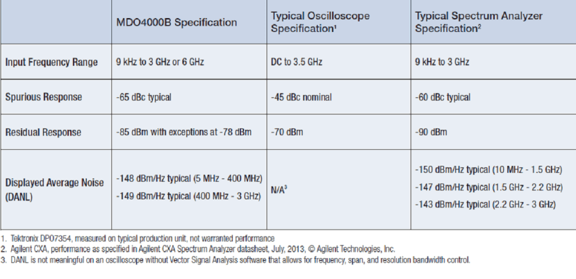
Superior Capability and Fidelity for Frequency Domain Measurements.The integrated spectrum analyzer in an MDO delivers superior fidelity relative to a scope with FFT. Some key specifications are compared in Table 1 and the technology used to get these results is described in the section below, “How an MDO Achieves its RF Performance”
Low noise performance is important for measuring low level signals, and out-of-band emissions for transmitters.
Large input frequency range: While oscilloscopes are available with bandwidths that can measure signals higher than 2 GHz, they are generally expensive and are not optimized for the sensitivity of RF analysis. The integrated spectrum analyzer in the MDO provides the performance required for typical RF signals without requiring the other analog channels to equal that performance. In addition, the spectrum analyzer input is specified differently from an oscilloscope input channel. While an oscilloscope’s analog input rolls off to -3 dB at its bandwidth rating, the spectrum analyzer input on the MDO has a flat response to its rated frequency of 3 or 6 GHz.
Superior fidelity. Spurious Free Dynamic Range (SFDR) indicates the ability for a spectrum analyzer to detect and measure small signals in the presence of large signals. The spurious response is a result of interactions between the user’s signal and the measuring instrument. They are difficult to “work around,” since their frequency and amplitude change with the changing input signal. Residual spurs are caused by signals generated within the measurement instrument leaking into the signal path. They are easier to identify, since they are generally static, but can be mistaken for spurs in the user’s signal. Because of their general purpose nature, oscilloscopes typically exhibit poorer SFDR than a spectrum analyzer.
Independent Hardware and User Interface Optimized for Frequency Domain Measurements. When using an FFT on a typical oscilloscope for making frequency domain measurements, the user interface is often the same one used for time domain measurements, or layered in menus under the FFT function. This makes it difficult to make typical spectrum analyzer adjustments, such as center frequency, span, and RBW. Furthermore, With a regular scope FFT, a single acquisition system is driven by a single set of acquisition parameters (time/div, record length, and sample rate) to acquire all data shown in all views. What this means is that the vast majority of the time you can optimize the acquisition system to show the desired time domain view or the desired frequency domain view but virtually never both at the same time.
By contrast, the MDO features two acquisition systems; one for the analog and digital channels and another for the spectrum analyzer. These independent acquisition systems enable the user to obtain optimal views in both domains.
The MDO provides dedicated front panel buttons for the most commonly performed spectrum analysis functions rather than the traditional FFT controls that are buried multiple layers deep in a menu structure. The numeric keypad allows easy entry of precise values.

The MDO spectrum analyzer display will look familiar and intuitive to spectrum analyzer users, with labeling of amplitude grid lines as well as start and stop frequencies, peak markers, and readouts of critical frequency domain parameters, including reference level, vertical scale, center frequency, span, and resolution bandwidth (RBW).
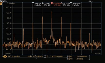
Key Spectrum Measurement Facilities
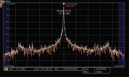
Many of the measurement features available on a stand-alone spectrum analyzer are also available on the spectrum analyzer in an MDO. Automatic markers can continuously track up to 11 frequencies with the highest amplitude. A number of automatic RF measurements are available including channel power, adjacent channel power ratio (ACPR), and Occupied Bandwidth measurements. The following figure shows an example of a channel power measurement:

MDO4000B Series Enables Synchronization of Analog, Digital and RF
The MDO4000B Series includes additional hardware, not included in the MDO3000, that provides system-level insight not available on any other instrument:
- The ability to simultaneously see time-correlated time domain waveforms and frequency spectrums
- The ability to see RF amplitude, phase or frequency versus time, synchronized with time domain waveforms
The analog, digital and spectrum analyzer input channels on an MDO4000B are all time-correlated. This allows the MDO4000B to show the timing relationships between, say, the serial data command to an RF transmitter and the resultant RF burst. A power supply voltage dip during a device state change can be analyzed and correlated to the impact on the RF signal.
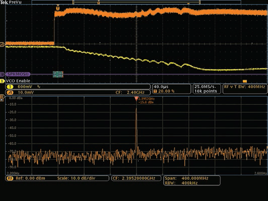
Let's see an example of an MDO4000B multi-domain screen and how time-correlated information is presented for analysis:

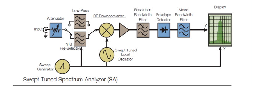
How an MDO Works


-
A much higher ADC sample rate which leads to exceptionally wide capture bandwidths
-
A small number of fixed downconversion ranges

- The data record is converted to a complex I (in-phase) and Q (quadrature) data format
- The center frequency is moved to DC, to allow the IQ sample rate to be reduced to half rate
- The data is filtered and decimated to a sample rate sufficient to cover the span
How an MDO Achieves its RF Performance
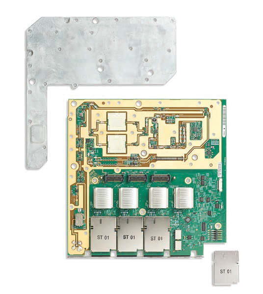
A dedicated, integrated spectrum analyzer provides better fidelity because the spectrum analyzer is dedicated to RF measurements, the design of the signal path is optimized for improved spectral fidelity.-
The BNC is replaced by a higher fidelity N connector and better interconnect to the circuit board.
-
Unlike a typical oscilloscope input, the spectrum analyzer input does not need to pass DC signals, nor does it need to provide offset capabilities. This allows the use of attenuator and amplifier components that are optimized for use in spectral applications.
- Significantly improved shielding is provided, as shown in this figure: