First PCB project - back to the drawing board!
Follow article
 Dave from DesignSpark
How do you feel about this article? Help us to provide better content for you.
Dave from DesignSpark
Thank you! Your feedback has been received.
Dave from DesignSpark
There was a problem submitting your feedback, please try again later.
Dave from DesignSpark
What do you think of this article?
Finding a number of faults with my first ever PCB design.
In a previous post I wrote about my first experiences with DesignSpark PCB, and sending my design to be manufactured.
I was pretty much thrown in at the deep end. Still very new to electronics, as a trainee, I had no previous experience in schematic capture or board layout, so this was initially quite a daunting prospect.
The PCBs arrive
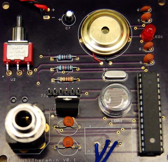
When the boards arrived from the manufacturer I gathered the required components, and then began to assemble PCB, starting with the smallest components and working my way to the largest.

When soldering the components in I noticed a couple of errors with the board. The first was that the footprint for C5 and C6 was far too big for the size of the capacitors I had. I didn’t see this as a major issue as long as the circuit worked fine.

Problems with the switch
I continued assembling the PCB until I came to soldering the switch in place. At this point I discovered two problems. Firstly, I realised the switch I had ordered was momentary and I needed one which would latch. The second issue was that the footprint on the board was orientated incorrectly and was going to intrude on where the jack socket would be placed.
I managed to find a solution to the problem by mounting the switch 180 degrees to the footprint. To do this I had to snip off the two legs on the front of the switch which were only used for mounting. I then fixed this in place using only a small amount of solder so that it could be more easily removed at a later date if needed.

Upon completion of soldering the components in I was excited to see if the PCB worked. Although I hadn’t programmed the ATMEGA at this point I tried to attach the battery as the LED on the board should illuminate when powered up.
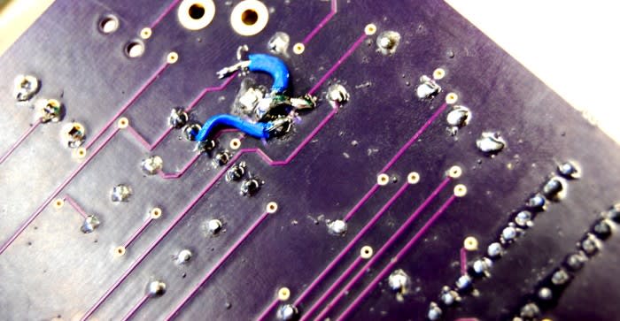
Incorrectly routed tracks
This was when I discovered the first major problem. I began testing the circuit with a voltmeter and realised I had connected the voltage regulator incorrectly; I had managed to get GND and OUT swapped in the schematic. So I decided to cut the tracks on the PCB and solder wire jumpers to re-route the tracks.
Programming the ATMEGA
At this point I decided to try powering up the board once again, and since the LED illuminated so I assumed everything was as it should be.
Next I programmed the ATMEGA using the Arduino IDE and a USB UART. When programmed I powered up the board and heard a dull humming sound. This did not sound at all like theremin, nor did it change pitch with varying light exposure to the LDR.
I decided to add a serial.print() to the sketch so that I could use the serial monitor to see what voltage was being read from the LDR. This displayed 0, indicating that something else must be wrong with the board.
I looked at the PCB in further detail, comparing against my original schematic and board layout. After a while I realised there were issues with some of the capacitor connections. It turned out that during schematic capture I had made a fundamental mistake, assuming that some lines were connected when they were not.
Looking at these mistakes it was clear that it would be too complicated and messy to manually cut the tracks and re-route them with wires. At this point I decided to give up on V0.1 of the light theremin project and make a start on V0.2.

Lessons well learned
As part of this experience I gained many invaluable lessons, from triple checking the properties of the components ordered and making sure the footprint is orientated correctly on your PCB, to being much more careful when using auto route!
Next time I'll print out my board layout and stick it to cardboard and check my components fit and are orientated correctly before sending it to be manufactured, and I’ll double check the tracks are routed correctly too. These were lessons well learned though and which can be timely and costly. However, I’ll be sure not to make the same mistakes again!