Painted Antenna Experiments Part 1
Follow article
 Dave from DesignSpark
How do you feel about this article? Help us to provide better content for you.
Dave from DesignSpark
Thank you! Your feedback has been received.
Dave from DesignSpark
There was a problem submitting your feedback, please try again later.
Dave from DesignSpark
What do you think of this article?

Initial experiments using Electric Paint to create simple antennas.
When I first saw Bare Conductive Electric Paint the application that immediately came to mind was using it to experiment with antenna design, since it would effectively allow you to sketch these out rather than have to construct them from metal rods or wire and suitably sturdy insulators etc.
In this post we take a look at creating a simple dipole tuned for the 1800MHz GSM band, which is convenient as such a design for this band is fairly small. It's also convenient as we have a licence for a particular channel in that band. However, if you wish to do something similar you will need to either use a frequency for which you are licensed, or else use an unlicensed band such as 433MHz.
Dipole design
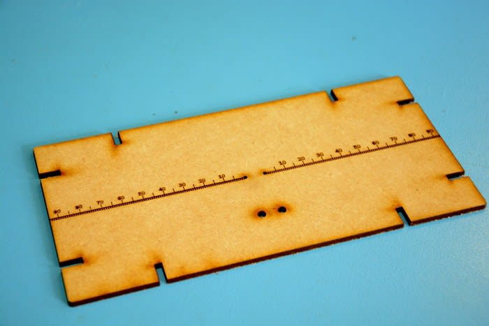
There are numerous variations on the dipole antenna, but here we will use the simplest and most common design, the centre-fed half-wave dipole. This is little more than two elements that are each one quarter wavelength long, oriented end-on-end and fed at the middle. In our case these elements will be painted onto a piece of 3mm thick laser cut MDF, with holes pierced for securing the coax feeder and an etched scale to make it easier to get the length of the elements right.
Now at this point I should note that the approach taken here is a somewhat rough and ready, and consideration has not been given to proper impedance matching. However, the hope is that we'll still get some useful results as we experiment with tuning the element length.
Test setup
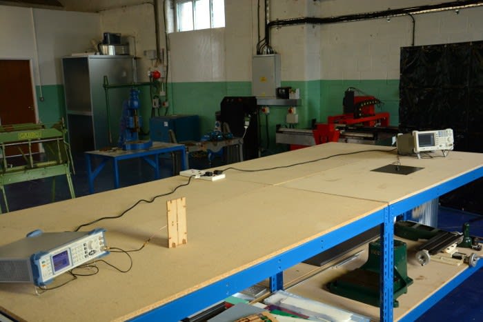
For the test setup we have a signal generator tuned to 1810.8MHz that provides a 0dBm signal — or thereabouts, considering there will be losses in the coax feeder etc. — to our painted antenna.

At the other end of the workbench, 2M away at the receiving end, we have a simple vertical antenna connected to a spectrum analyser.

Of course, to do this properly would require access to an anechoic chamber in order to ensure that there are no signals being reflected from walls, equipment and people etc. influencing the experiment. Although the nearest I could manage was an empty workbench out in the metal workshop! But once again, we should at least get some useful indication with this setup.
Testing
A quarter wavelength at 1810.8MHz is 39mm and for the first test I decided to paint elements that were a good bit shorter at 30mm each in length.
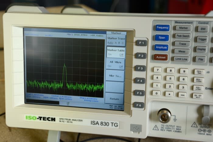
With this the signal level measured at the spectrum analyser was -68.6dBm.
Now I had a starting point I lengthened the elements out to 39mm each.

This resulted in a slightly stronger signal measured at -56.9dBm.
But what if they were lengthened out again, surely the received signal strength would increase once more? I lengthened each element out to 60mm in order to find out.
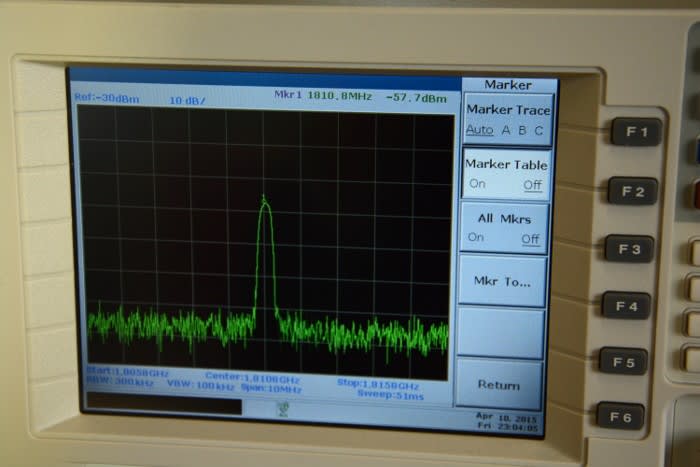
Doing this resulted in the received signal level dropping a little, to -57.7dBm. Which is as I'd hoped, as the antenna became electrically longer but detuned and thus less effective.
Conclusion
As mentioned previously, the test setup used was rather rough and ready and when taking measurements the received signal level could be seen to fluctuate a little as I moved around. Aside from using an anechoic chamber there are likely other simpler improvements that could be made to the setup and/or process, and more thought given to antenna construction (my first efforts with the Electric Paint were a bit messy), impedance matching and so forth.
However, the initial results are encouraging and next time I will probably try making some more interesting antenna designs, which would be harder and certainly more time consuming to prototype without the aid of conductive paint.