Design of an Analog Car - CarBody
Follow article Dave from DesignSpark
How do you feel about this article? Help us to provide better content for you.
Dave from DesignSpark
Thank you! Your feedback has been received.
Dave from DesignSpark
There was a problem submitting your feedback, please try again later.
Dave from DesignSpark
What do you think of this article?

In order to improve the laboratory of EE2109 of City University, we are requested to combine and design a new laboratory of it. In EE2109, students will learn about transistor, operational amplifier, diode, and filter. To combine these technologies and design a interesting laboratory, we decided to design a basic simple Analog Car circuit.
Before reading this article, you may first read about another article called Design of an Analog Car – Remote.
Design
For a basic Analog Car, it should have two wheels that controlled by two signals. Therefore, we only need two things and they are signal emitter and receiver. As we have discussed about the signal emitter in the passage of Design of an Analog Car – Remote, we will focus on the signal receiver – Car Body in the following.
For a signal receiver – Car Body, we need to have two receivers to control two wheels to on or off. For example, we use a photodiode as a receiver, it can receive the signals generated from the LED bulb of Remote. A high pass filter can be used to reduce the effects of noise. To ensure the signal is strong enough, an amplifier is required to enlarge the gain of signal. Moreover, we need to select the signals that we want so a narrow band pass filter can be used. As we have chosen 5kHz and 1kHz in the remote, we should set up two narrow band pass filter that can only filter out 5kHz and 1kHz. After selecting the signals, we may use a full wave rectifier and a low pass filter to convert the AC signal to DC signal. Finally, we use a comparator to control the reference voltage that is connecting to a transistor to turn on the motor.

Material List:
|
R.S. part number |
Manufacturer |
Manufacturing number |
Description |
Quantity |
|
522-2693 |
Bourns |
3386P-1-103LF |
Variable resistor 10K
|
2 |
|
522-2801 |
Bourns |
3386P-1-504LF |
Variable resistor 500K
|
2 |
|
761-3546 |
Fairchild Semiconductor |
LM358N |
IC |
1 |
|
661-0530 |
Texas Instruments |
LM324N |
IC |
2 |
|
699-7610 |
Vishay |
BPW41N |
IR Photodiode
|
2 |
|
670-8858 |
Fairchild Semiconductor |
1N4148 |
Diode |
8 |
|
744-2202 |
RS |
744-2202 |
9V battery
|
1 |
|
752-1999 |
Como Drills |
951D6016V |
DC Motor
|
2 |
|
714-0442 |
STMicroelectronics |
2N2219 |
Transistor
|
2 |
Breadboard:
To check whether it is work or not, we first need to test it on a breadboard. We put all the components on a breadboard, there are some problems occurred. For example, the gain is not enough that means the motor cannot turn on. On the other hands, the sensitivity of the photodiode is also too weak. After debugging, we have modified the circuits and changed some of the components. As a result, it works with a signal emitter on a breadboard.

Schematic:
After the first test on the breadboard, we try to draw the schematic of the circuit on computer. By using the Design Spark PCB, we can find most of the components from its powerful libraries. However, some components such as Motor do not exist so we need to draw it ourselves.

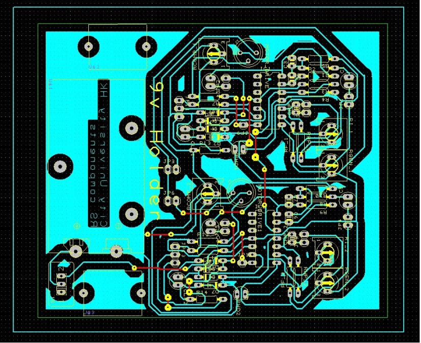
PCB
Using the Design Spark PCB again, we can convert the schematic to PCB layout. Then print the layout and buy a copper board. After PCB fabrication, the PCB is created. Before to drill the holes for components, we need to check whether any copper routes missing. After that, we can drill all the holes and weld all the components on the PCB.
After welding all the components on the PCB, we can use the CRO and signal generator to check whether it can receive the signals and filter out the selected frequencies. Moreover, the variable resistor can be used to adjust the gain of the received signals. For example, we use the signal generator in the laboratory to generate a 5kHz signal and a 1kHz signals that pass though two LED bulbs. As a result, the photodiodes can receive the signals and the filters can select the correct frequencies. The motors turn on.

Conclusion
If you are following what we did above, you will get a signal receiver and that is the Car Body. However, if you want to design your own circuit, you can modify the circuit. To design you own circuit, remember to match the Car Body circuit with the Remote circuit. Otherwise, the Analog Car will not work. Design to enjoy, enjoy your designing. Thank you.
This article is only including the Car Body part of the Analog Car. For the Remote part of the Analog Car, you may refer to another article.

Products
When you have completed what we did before, you should have two circuits now. They are the Remote and Car Body part.
For the Remote, you should have two switches to control the on/off of two LED bulbs. Also, some variable resistors exist to control the gain and strength of LED bulbs.
For the Car Body, you should have two photodiodes to receive two signals. Also, some variable resistors exist to control the gain. Two motors are connected to the circuit.
When you turn on one of the LED bulb on the Remote, one motor on the Car Body should be also turn on. When both of the LED bulbs turn on, both motors on the Car Body should be also turn on.
