Control wireless mains sockets with Arduino and Raspberry Pi
Follow article
 Dave from DesignSpark
How do you feel about this article? Help us to provide better content for you.
Dave from DesignSpark
Thank you! Your feedback has been received.
Dave from DesignSpark
There was a problem submitting your feedback, please try again later.
Dave from DesignSpark
What do you think of this article?
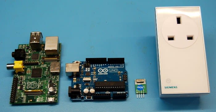
LightwaveRF (LWRF) is a range of switches, dimmers and other home automation hardware that is widely available in the UK and further afield, sometimes sold under other brands such as Siemens. They are affordable units that are easy to work with.
Working with off-the-shelf products, such as remotely switchable mains sockets, means that we can concentrate on control without having to deal with mains voltages directly.
A set of 3 switchable mains sockets can be bought for around £20 – including a remote that appears to be compatible with up to 16 switches in total. Here we will replace this remote with our own wireless hardware, so that we can have programmable control.
The LightwaveRF protocol
One great thing about the LWRF protocol is that it fairly simple and has already been reverse engineered by people looking to build their own home automation systems. This means that we can use readily available libraries and examples to quickly interface a microcontroller or computer with the hardware.
The LWRF system operates on 433 MHz and uses simple On/Off Keying (OOK) modulation, whereby the carrier is turned on and off to transmit information. Low cost transmitter modules suitable for use with Arduino and Raspberry Pi are commonly available.
Arduino control
Hardware required:
-
Prototyping breadboard
-
Jumper wires
-
LWRF mains socket
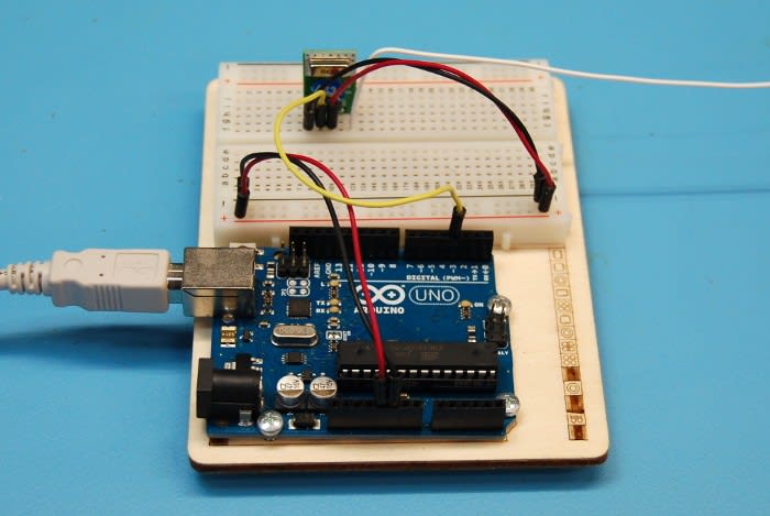
First we will connect the radio module.
The QAM-TX1-433 module has 4 pins:
-
ANT (Antenna) – a 174mm length of solid core wire makes for a suitable antenna.
-
VCC – 5v from Arduino.
-
DATA – Arduino pin 3 for the unmodified 'lwsend' sketch.
-
GND – ground connection to the Arduino board.
We'll be using the excellent LightwaveRF library written by Lawrie Griffiths. Add this to your Arduino libraries folder and upload the 'lwsend' example to your Arduino.
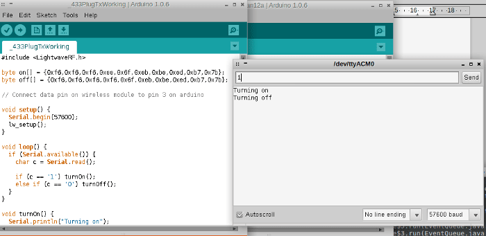
Now open the serial monitor and try sending '1' or '0' to the Arduino. If this looks to be working, try pairing the Arduino to the LWRF socket by putting the socket in 'pairing mode' (see the supplied instructions) and sending '1' over the serial monitor to the Arduino, so that the 'on' command is sent.
The 'lwsend' sketch is pre-configured to transmit compatible LWRF on/off control signals. If the pairing was successful you should now be able to turn the socket on and off with your Arduino.
Raspberry Pi control
Hardware required:
-
Raspberry Pi (any model)
-
Prototyping breadboard
-
Jumper wires
-
LWRF mains socket
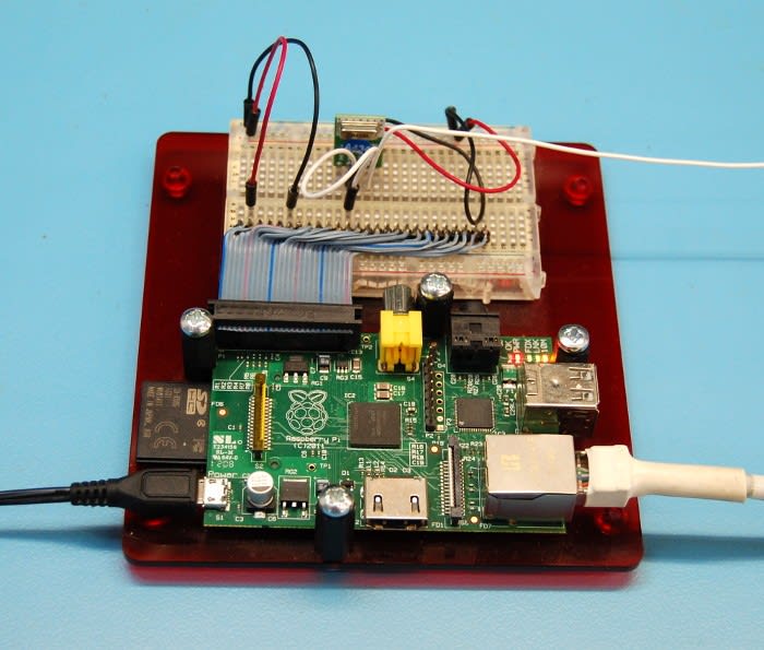
The same wireless module (QAM-TX1-433) is used in much the same way we did with the Arduino:
-
ANT (Antenna) – a 174mm length of solid core wire makes for a suitable antenna.
-
VCC – 5v from Raspberry Pi.
-
DATA – Pin 12 on connector P1for the unmodified lightwaverf-pi 'send' program.
-
GND – ground connection to the Raspberry Pi.
Here we will use a version of Lawrie's LightwaveRF Arduino library that has been adapted for use with Raspberry Pi.
This port makes use of the WiringPi library, which simplifies the use of GPIO on the Raspberry Pi and provides a familiar environment for Arduino developers.
Install the WiringPi library by following the instructions here. Next add the LightwaveRF-pi files and compile by following the instructions here. Now you should have two executables that can be used to send the correct 'on' and 'off' signals to control the socket.

Summary
Now it is possible to use an Arduino or Raspberry Pi to control wireless mains sockets, this capability can be easily integrated into custom Arduino and Linux-based home automation projects.
With a little extra work it is also possible to control multiple sockets, dimmers and other LWRF home automation products. For details of the LWRF protocol see: